Choosing the right Wound Rotor Motor in 2026 requires more than comparing rated power and purchase price. Global buyers must examine starting torque, speed control, duty cycle, enclosure design, maintenance access, and regional service capability. A cement conveyor may need smooth acceleration under heavy load. A shipyard crane may demand repeated starts without excessive rotor heating. The application decides the motor type.
Professor Austin Hughes, a respected author on electric motors and drives, stated, “The wound-rotor motor is used where high starting torque is required.” That principle remains practical. External rotor resistance can limit starting current while producing strong torque. It can also support controlled acceleration in mining hoists, crushers, elevators, and large pumps. However, resistance grids create heat and require inspection. That cost is easy to overlook.
This guide compares slip-ring, liquid-resistance, brushless, and modern retrofit-oriented Wound Rotor Motor solutions for international purchasers. It considers efficiency, installation conditions, spare-parts availability, control-system compatibility, and long-term operating risk. Technical brochures often look impressive. Field conditions are less tidy. Dust enters cabinets. Brushes wear unevenly. Cooling performance changes with altitude and ambient temperature.
No ranking is perfect. A motor that performs well in a clean factory may struggle beside a hot, dusty kiln. Buyers should verify test data, supplier experience, warranty terms, and local technical support before approving a purchase. The strongest choice is not always the newest design. It is the one that delivers dependable torque, manageable maintenance, and measurable value over its operating life.
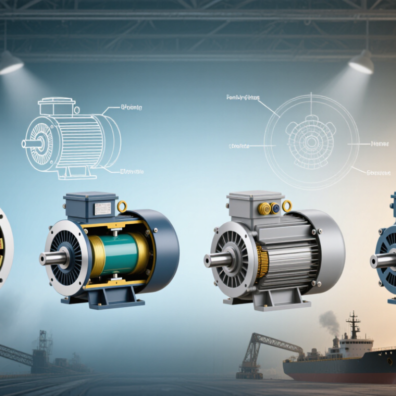
A wound rotor motor uses a laminated stator and a rotor carrying insulated three-phase windings. Those rotor windings connect to slip rings and brushes, allowing external resistance into the circuit. This arrangement changes the motor’s starting behavior, not its basic electromagnetic foundation. When three-phase power energizes the stator, a rotating magnetic field induces current in the rotor. Torque appears as the rotor field follows the stator field, always with some slip. The rotor is not locked. It is adjustable.
At startup, external resistors limit current and increase effective rotor resistance. This can deliver high starting torque for cranes, hoists, mills, conveyors, and other heavy-load applications. As speed rises, resistance is gradually reduced or shorted out, improving running efficiency. The motor then operates more like a conventional induction motor, although brush and ring losses remain. Adjustment is practical. Continuous resistance control, however, can waste energy as heat.
For global buyers, nameplate data deserves close reading: rated voltage, frequency, power, duty, insulation class, enclosure, altitude, and ambient temperature. The control resistor, starter, and cooling method must match the motor’s current and torque demands. Maintenance teams should inspect brush wear, ring surfaces, connections, bearings, and ventilation intervals. A dusty site may need stronger enclosure protection, while humid locations require careful condensation control. The theory looks clean; field conditions are not. Extra hardware increases cost and maintenance. Specifications should never be treated as decoration.
| Motor Type / Configuration | Operating Principle | Typical Starting Torque | Starting Current | Speed Control Capability | Typical Applications | Main Advantages | Main Limitations |
|---|---|---|---|---|---|---|---|
| Standard Slip-Ring Motor with External Resistance | Rotor windings are connected to stepped external resistors during starting. Resistance is gradually reduced as the motor accelerates, and the rotor is short-circuited near rated speed. | Approximately 2.0–3.0 × rated torque, depending on rotor resistance and design. | Usually lower than direct-on-line squirrel-cage starting for the same starting torque; the exact value depends on the resistor steps and supply system. | Limited and stepped control through rotor resistance; not normally used for efficient continuous speed regulation. | Cranes, hoists, conveyors, crushers, mills, pumps with high breakaway torque, and heavy starting loads. | High starting torque, reduced mechanical shock, and lower supply-current impact than some direct-start methods. | Brush and slip-ring maintenance, resistor heat losses, larger maintenance requirements, and higher purchase cost than many squirrel-cage motors. |
| Liquid-Rotor-Resistance Motor | An electrolyte-based liquid resistor is inserted into the rotor circuit. Increasing or decreasing the immersed electrode area changes the rotor resistance and starting torque. | Often adjustable up to approximately 2.5–3.0 × rated torque when correctly designed. | Smoothly controlled and generally limited by the selected rotor-resistance profile and the supply network. | Smooth starting and short-duration speed adjustment; continuous speed control is inefficient because energy is dissipated as heat. | Large conveyors, ball mills, crushers, fans, pumps, and high-inertia industrial machinery. | Smooth acceleration, high starting torque, reduced torque pulsation, and suitability for large motor ratings. | Electrolyte monitoring, cooling, enclosure protection, corrosion control, and periodic maintenance are required. |
| Rotor-Resistance Starter with Automatic Contactor Steps | Multiple resistor sections are bypassed sequentially by contactors or switching devices as rotor speed rises. | Approximately 1.8–3.0 × rated torque, depending on the number of steps and resistance values. | Controlled to reduce voltage drop and current peaks during acceleration. | Stepped acceleration only; the motor normally operates at near-rated speed after the rotor is short-circuited. | Material-handling equipment, hoists, elevators, conveyors, compressors, and rolling equipment. | Repeatable starting sequence, relatively simple control logic, and flexible starting-time adjustment. | Contact wear, switching transients, resistor heating, and limited efficiency during the starting period. |
| Wound Rotor Motor with Soft Starter on the Stator | A thyristor-based soft starter controls the stator voltage during acceleration, while the rotor circuit is configured according to the motor design. | Typically lower than full-voltage starting; available torque depends strongly on the voltage ramp and load profile. | Reduced during starting, commonly adjustable by setting the voltage ramp and current limit. | Smooth acceleration and deceleration, but not full variable-frequency speed control. | Pumps, fans, conveyors, compressors, and applications requiring reduced mechanical shock. | Reduced inrush current, programmable ramping, and less mechanical stress on couplings and gearboxes. | May not provide sufficient breakaway torque for very high-inertia loads; harmonic effects and heat generation require evaluation. |
| Wound Rotor Motor with Variable-Frequency Drive | The drive varies stator frequency and voltage to control synchronous speed and motor flux. The rotor circuit must be compatible with the selected drive arrangement. | Can provide high starting torque, commonly up to approximately 1.5–2.5 × rated torque, subject to drive and motor limits. | Generally controlled and substantially lower than direct-on-line starting, depending on the drive settings. | Wide continuous speed range; practical range depends on cooling, torque requirements, motor insulation, and drive configuration. | Conveyors, hoists, test stands, process lines, pumps, fans, and systems requiring process-speed adjustment. | Efficient speed control, controlled acceleration, regenerative or braking options, and improved process flexibility. | Higher system complexity, electromagnetic-compatibility requirements, drive-related losses, and the need to verify slip-ring and insulation compatibility. |
| Double-Cage or Deep-Bar Comparison Option | This is a squirrel-cage rotor design rather than a wound rotor. Rotor-bar skin effect improves starting performance without external slip rings. | Typically approximately 1.5–2.5 × rated torque, depending on the design. | Usually higher than a wound rotor with external resistance when very high starting torque is required. | Requires a soft starter or variable-frequency drive for advanced starting and speed control. | Fans, pumps, compressors, conveyors, and general industrial drives where low maintenance is important. | No brushes or slip rings, lower maintenance, compact construction, and strong operational reliability. | Normally offers less adjustable starting torque than a wound rotor with external resistance. |
| Parameter | Technical Description | Typical Engineering Range or Value | Buyer Evaluation Point |
|---|---|---|---|
| Rotor Construction | The rotor contains a three-phase insulated winding placed in a laminated core. The winding is connected to slip rings mounted on the shaft. | Three-phase rotor winding; rotor voltage and current are specified at standstill and vary with operating condition. | Confirm insulation class, rotor voltage, rotor current, slip-ring material, and brush arrangement. |
| Slip | Slip is the difference between synchronous speed and rotor speed expressed relative to synchronous speed. Rotor current frequency equals slip frequency multiplied by stator frequency. | Rated-load slip is commonly about 1%–5%, depending on motor size and design; starting slip is 100%. | Lower rated slip generally indicates lower rotor copper loss, but load torque and thermal limits must also be considered. |
| Synchronous Speed | The rotating magnetic-field speed is determined by supply frequency and the number of stator poles. | Formula: ns = 120f / P, where ns is rpm, f is frequency in hertz, and P is the number of poles. For example, a four-pole motor runs at 1,500 rpm synchronous speed on 50 Hz supply. | Check compatibility with 50 Hz or 60 Hz grids and the required operating speed. |
| Torque Control by Rotor Resistance | Adding resistance to the rotor circuit can increase starting torque and reduce starting current. Maximum torque is approximately maintained while the slip at maximum torque increases. | External resistance is normally removed progressively as speed rises. | Specify acceleration time, load inertia, breakaway torque, permissible current, and number of starting operations per hour. |
| Efficiency | Efficiency depends on motor size, load, rated speed, ventilation, and rotor-circuit losses. External resistance converts slip energy into heat during starting or speed control. | Large motors may achieve high full-load efficiency, but resistance-based speed control reduces system efficiency. | Use a variable-frequency drive or energy-recovery system when continuous speed regulation is required. |
| Protection and Enclosure | Protection must address overload, short circuit, phase loss, earth fault, overspeed, bearing temperature, winding temperature, and slip-ring access. | Common enclosure selections include IP23 and IP55, but the correct rating depends on the installation environment. | Match the enclosure, cooling method, ambient temperature, altitude, dust, moisture, and hazardous-area requirements. |
| Common Standards | Motor design, testing, efficiency, dimensions, and protection may be specified using internationally recognized standards. | IEC 60034 series, IEEE 112, NEMA MG 1, and relevant local electrical codes are commonly referenced. | State the required standard, efficiency class, test method, tolerances, and certification documents in the purchase specification. |
It has a laminated stator and a rotor with insulated three-phase windings. Slip rings and brushes connect the rotor circuit to external resistance. The rotor is adjustable. It still operates through electromagnetic induction and slip.
External resistance limits rotor current and increases starting torque. This helps heavy loads begin moving smoothly. Cranes, hoists, mills, and conveyors may benefit.
Resistance is gradually reduced or shorted as speed rises. Running efficiency then improves. However, brush, ring, and starter losses remain.
Yes. Resistance can convert useful electrical energy into heat. The heat may require additional cooling. This approach is practical, but not always efficient.
Check voltage, frequency, power, duty, insulation class, enclosure, altitude, and ambient temperature. These details affect starting, cooling, and insulation life. A nameplate is not decoration.
Dust can block ventilation and damage exposed surfaces. Humidity can create condensation near insulation and connections. High altitude and heat can reduce cooling capacity. Field conditions are rarely perfect.
Inspect brushes, slip rings, connections, bearings, and ventilation paths. Dusty areas may need shorter inspection intervals. Neglected rings can cause rough starting and poor electrical contact.
Compare operating duty, torque curves, starter losses, rotor losses, and part-load behavior. Review vibration data, thermal limits, and duty-cycle tests. Local service capability also matters.
No. It can provide smooth, high starting torque, but extra hardware increases cost and maintenance. Alternative speed-control equipment may remove brushes, yet it can cost more. The choice may remain imperfect.
A Wound Rotor Motor is an induction motor designed with a rotor winding connected to external resistance through slip rings. This structure allows operators to control starting current, increase starting torque, and achieve smoother acceleration for demanding loads. In 2026, global buyers can compare several configurations, including standard wound rotor motors, slip-ring motors with adjustable resistance, and application-focused designs for cranes, conveyors, mills, pumps, and heavy processing equipment. Each type offers different advantages in starting performance, speed control, maintenance requirements, and operating efficiency.
When comparing options, buyers should evaluate rated power, torque characteristics, duty cycle, enclosure protection, cooling method, efficiency, service conditions, and expected maintenance workload. Voltage and frequency must match the local electrical network, while insulation systems, safety features, documentation, and regional compliance requirements should be confirmed before purchase. The best selection balances starting demands, environmental conditions, installation space, lifecycle cost, and available technical support, ensuring reliable operation and practical long-term value across international applications.

 NANFANG